|
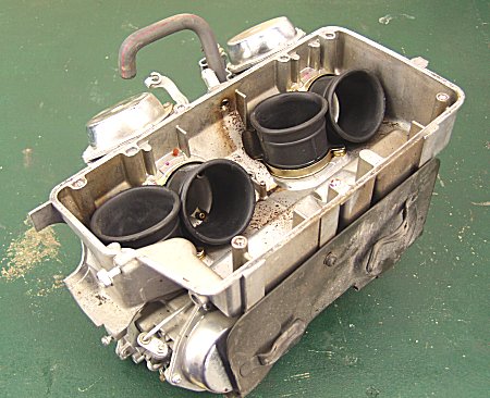
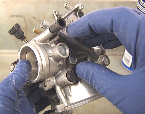
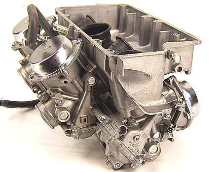
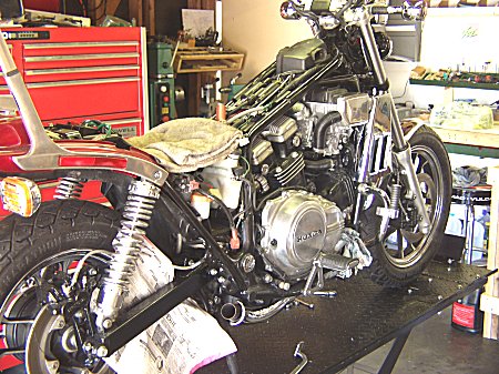
Pretty compact carbs, eh? Only Keihin and Honda could do something like this!
|
|
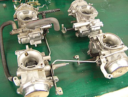
Haven't seen any other problems. Carbs look very good in terms of rebuildability. More info later!
|
|
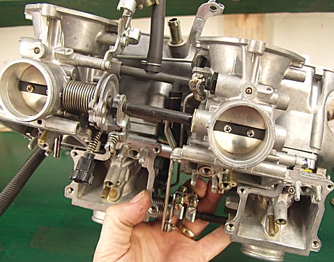
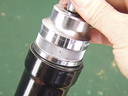
These are extremely delicate carbs. Many of these on eBay are broken, because unless you have been around them before, you don't know how fragile they can be. Thin aluminum casting, plastic abounds.
|
|
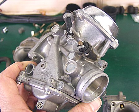
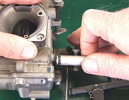
Aluminum throttle shafts. Can't be rough with these carburetors.
|
|
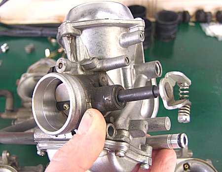
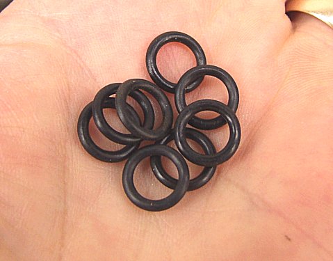
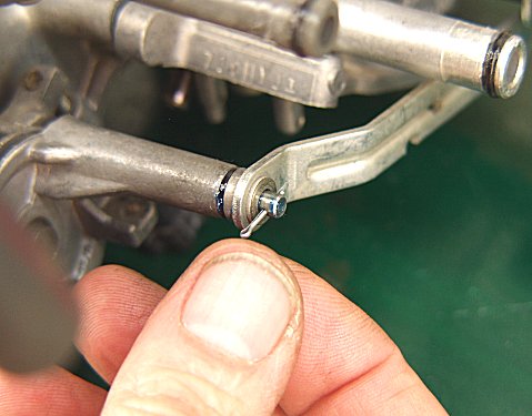
Here are the o-rings I mentioned before. Surprisingly, they were actually pretty tight. That is the issue, they age, harden, and shrink, leading to fuel leaks.
|
|
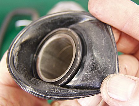
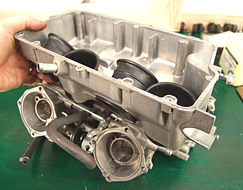
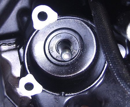
This is one of the four carb slide diaphragms. These diaphragms do all the work of moving the slide up and down. Until about 1982, it was common for these to get tears in them. Newer designs like these latex based ones are much more durable, but it's still wise to check them.
|
|
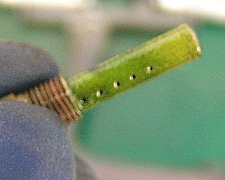
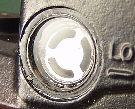
Thought you might like to see inside the carb. This is the main emulsion tube, just under the main jet. Note how green! Fuel turns ugly when it sits a long time.
|
|
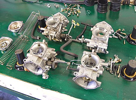
Carbs completely apart, ready for closer inspection, cleaning, circuit testing, assembly, final testing and adjustment.
|
|
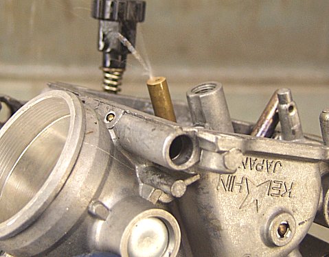
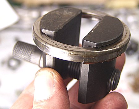
Special tools used to block off parts of passages to build pressure while flushing out circuits.
|
|
So that we can see this! Jet stream!
|
|
New o-rings for the casting-to-casting mating joints.
|
|
O-rings installed and being lighly lubed with thin grease, an important detail for assembly without pinching the o-rings.
|
|
More attention to detail in new cotter pins.
|
|
Airbox base going back on. This part actuall serves two jobs besides holding the air filter later. It lines up all the carburetor castings so that the linkage and interconnecting pipes are aligned, and it is the only provision (but a good one) for making the finished assembly rigid and complete. A nice piece of multiple purpose technology, and one of the reasons these carbs are so lightweight.
|
|
A final check of the linkage, including throttle butterflies, before the main bolts are tightened down.
|
|
Here the carbs are fully assembled, adjusted, (cleaned of course), and leak-tested prior to reinstallation.
|
|
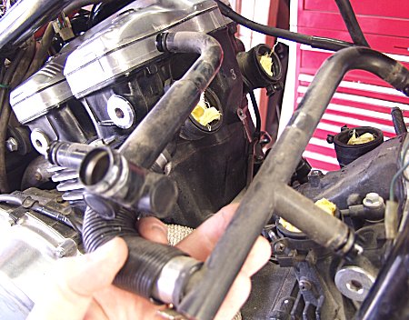
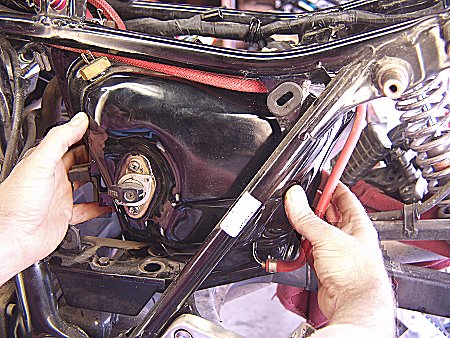
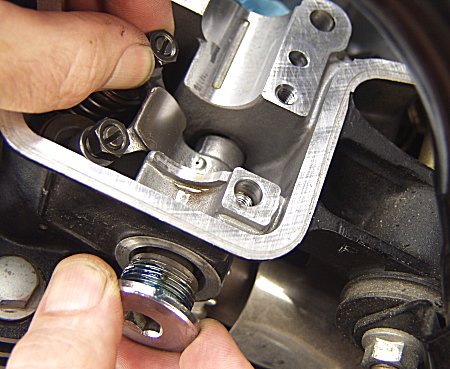
But before we reinstall the carburetors, we must deal with something that will crop up once the bike is back on the road, and that is the coolant passage gaskets. The carbs have to be removed to get to them, so we want to preemptively service them now.
|
|
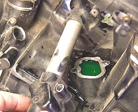
Here you can see the main gallery.
|
|
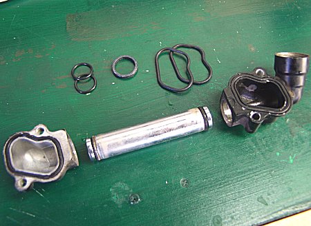
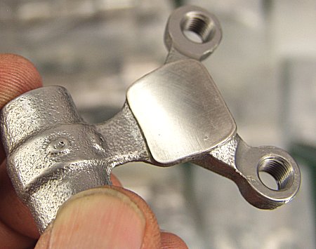
And here we have the parts in question, with their new o-rings.
|
|
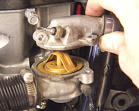
Replaced the thermostat while we're in the area.
|
|
Removed the fuel tank to get a good look in it. Was in the area anyway to work on brakes and electrical and fuel lines. All in the same area.
|
|
Basically it's a rear of the bike day today. :-) I have some things to email you about today, so I might as well get to it.
|
|
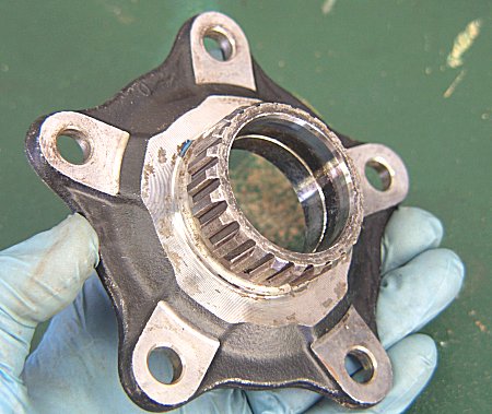
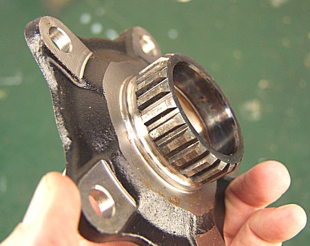
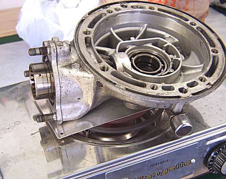
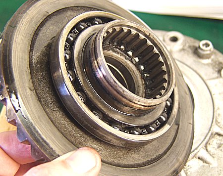
Okay, the next few pix are of the infamous final drive driven and drive flange. Those are the Honda official names for the parts. Here we have a wide shot of the driven flange, the subject of much instruction and warning by Honda re the Gold Wing and V4 series. It is removable from the wheel, as you can see here.
|
|
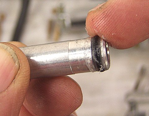
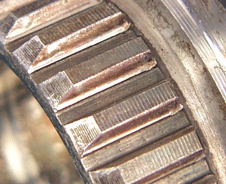
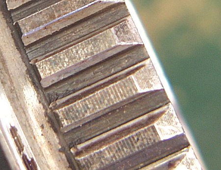
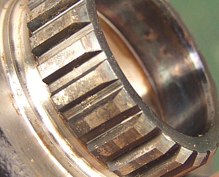
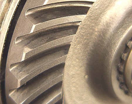
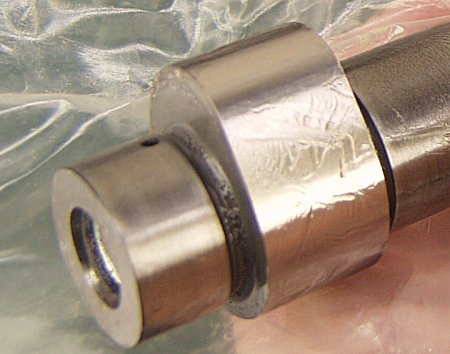
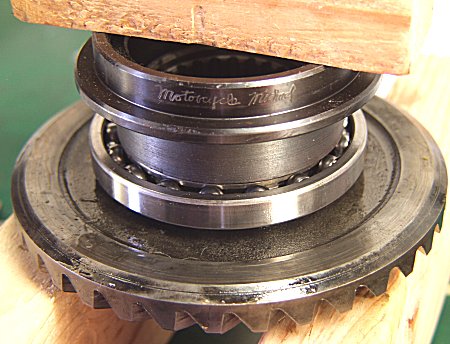
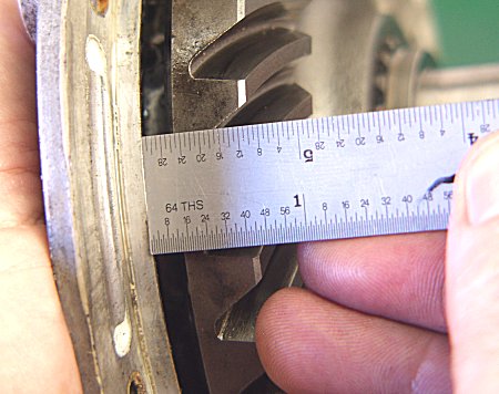
In this close-up, you can clearly see that one side of the splines is worn, as I say, about 1mm (0.040"), maybe a little more. The wear is only on the side of the spines that is driven forward by the drive spline. The trailing edge, in other words.
|
|
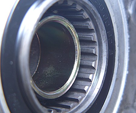
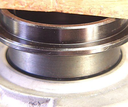
In this close-up, the flange has been turned around for a shot of the leading edge, the side of the individual splines that does not get pushed against. No wear on the leading edges of the splines. (Too bad we can't just flip the part around to get more wear life, eh?)
|
|
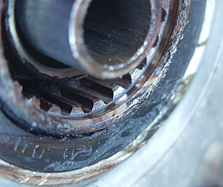
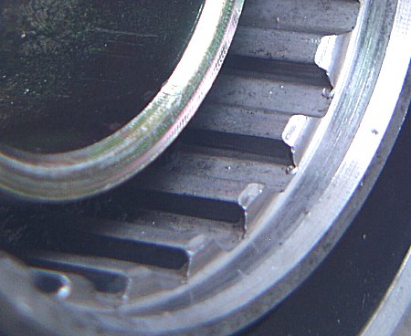
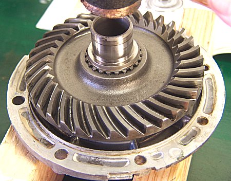
This is a medium shot of the mating, drive side, of the spline assembly, that in the drive unit itself. I have cleaned up the splines (teeth) and have brought in four different lights to try to draw out the details.
|
|
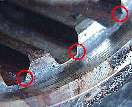
In this close-up, which is not all that good, you can just discern some wear. The red circles point out the irregular curve to the left of each spline. That is, slight hooking or added radius. Better light would also show that this continues all along the spline as you move inward into the unit. This is the contact side, the driving side of the individual spline. The wear is confirmed with a sharp pick tool, which catches at this point. The wear here is about half or even less what we see in the drive half of the assembly, probably because being one with the ring gear, the part is made to a higher hardness value. The wear is admittedly pretty slight, though it can be seen, barely, and a pick catehes it. One option might be to replace the driven flange, the easy one, and simply monitor the wear on the drive spline, this one, that is part of the drive unit itself (actually one with the ring gear). That would be my recommendation.
|
|
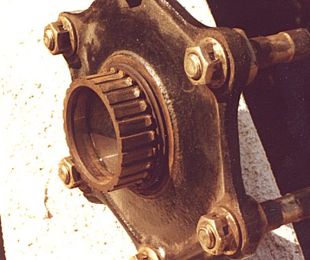
I dug up this 25-year old image to show you what a neglected driven flange looks like. Wow! Poor photography, I can admit since it was my own. Taken at a Honda dealer I worked at in 1983. Note the mounting method on the earlier flanges is floating pin, not bolts like on your bike.
|
|
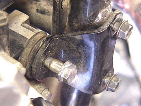
Same roll of film, same bike probably (750 Magna), showing part of the special alignment procedure that must be performed each time the wheel is removed and replaced. That is the mounting stud (and nut) for the final drive attachment to the swingarm.
|
|
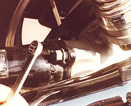
Rear brake master cylinder finished, going on to the rest.
|

|
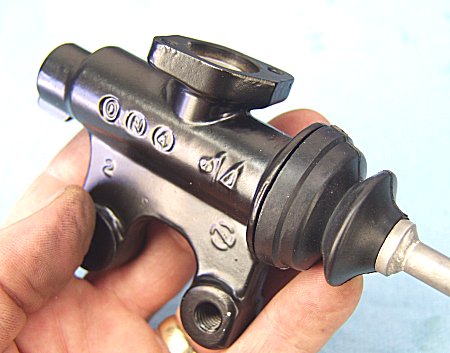
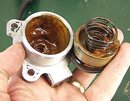
Thought you might like to see what was inside your clutch master cylinder. Yuck!
|
|
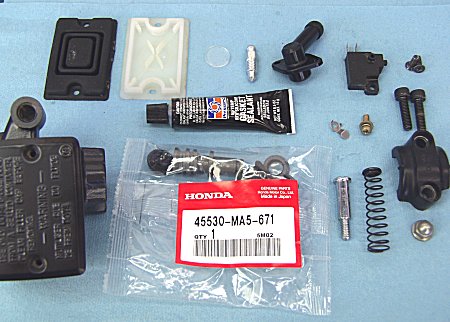
Getting ready for the clean assembly.
|
|
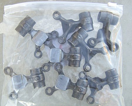
Rockers (followers) all removed, stipped, cleaned and bagged, ready for shipping.
|
|
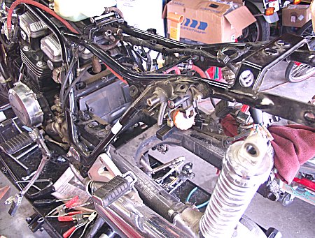
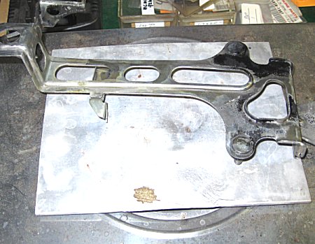
The engine has to be loosened in the frame, and the removable frame rail on the left side practically removed, in order to get two of the eight followers out.
|
|
Here's the new final drive driven flange. The NOS one from UK (David Silver Spares).
|
|
And here is a close-up.
|
|
The eBay final drive unit. Which, happily, turns out to be very low miles, although when first opened up we could see the previous owner never changed his fluid. Ugh!
|
|
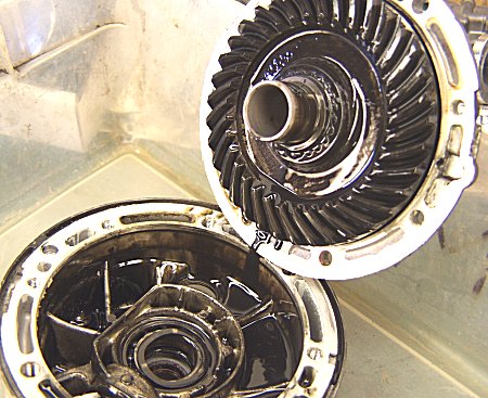
Despite this care, we are looking at a very nice unit. Here is the ring gear, with very little wear.
|
|
And here is the all-important part (the reason for getting this final drive unit assembly), the final drive flange. Again, just what we were hoping for. Praise God.
|
|
A close-up. Less wear than yours. So what we'll do is change out your whole unit with this one.
|
|
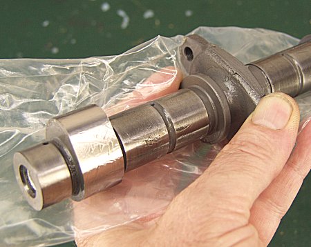
Thought you might want to see the cams. Beautiful!
|
|
And up close. That's preservative grease on the lobe.
|
|
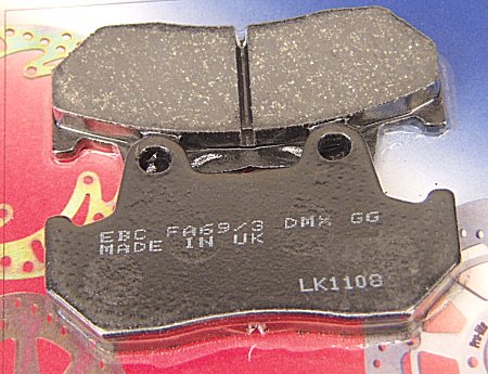
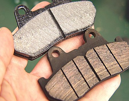
Finally found you some organic (i.e. non-metallic) brake pads. At a good price too.
|
|
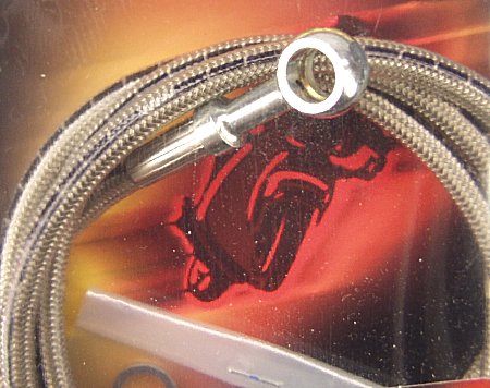
And the nice braided lines for all five hose replacements (including clutch line).
|
|
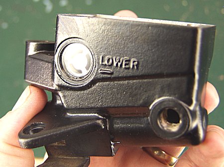
Here's one of the master cylinders rebuilt. Note the new level sight window, an aftermarket part I just found available. The original window was badly decayed.
|
|
A close-up. The new window is actually glass, instead of the original plastic.
|
|
Taking the rear drive apart. Heating on hotplate first.
|
|
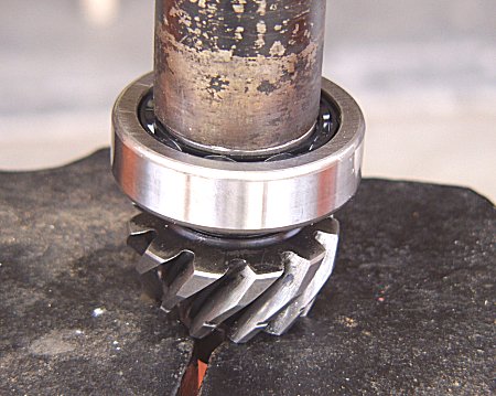
Now the pinion gear can be removed and inspected.
|
|
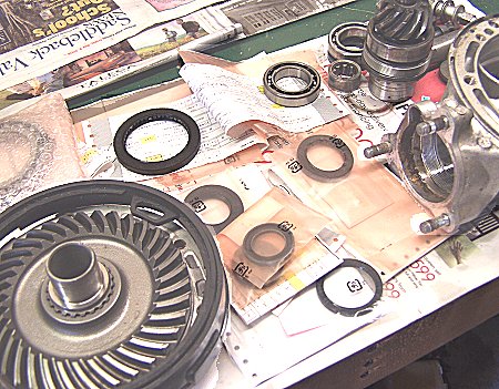
A lot of parts in that ziplock bag, but missing a few seals, so those get ordered.
|
|
Removing the ring gear with its bearing, from the plate.
|
|
New bearing going on the ring gear.
|
|
New seal following after, onto the mounting plate.
|
|
Ring gear going back into plate.
|
|
Measuring all the way around the ring gear to ensure it is installed square to mounting plate.
|
|
Putting in the softer organic brake pads. That's the scratchier metallic pad on the bottom of the picture.
|
|
Starting on the clutch hydraulic system now.
|
|
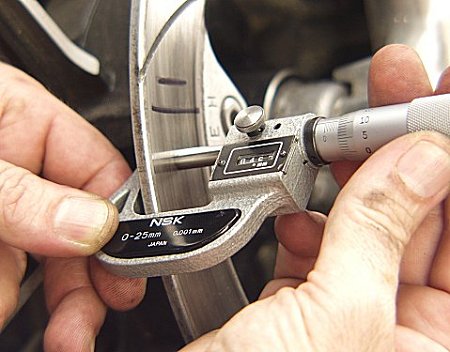
Did the inspection on the brake discs. They're in good shape. Under 0.10mm thickness variation and runout.
|
|
Megacycle reconditioned followers going in.
|
|
They did a really nice job on these by the way. Very pretty.
|
|
Cam chain tensioners going in.
|
|
Then the cams, with a lot of the Megacycle break-in lube, which they highly recommend.
|
|
Finishing up the cylinder heads and torquing it all up.
|
|
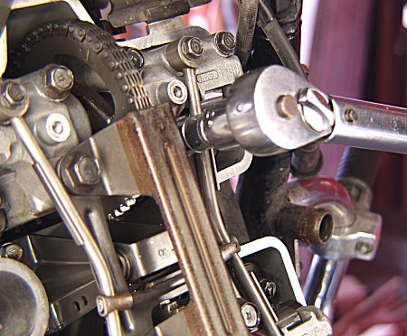
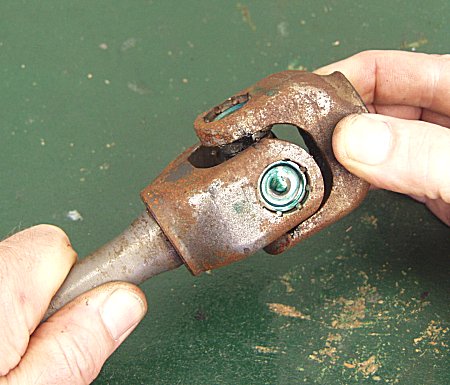
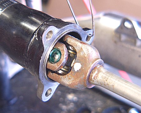
While the driveshaft is out, checking the u-joint. Looks good.
|
|
Replacing the seals and bearings.
|
|
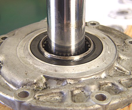
Hear is the pinion shaft bearing getting replaced.
|
|
And here we're replacing the seal on the driveshaft damper.
|
|
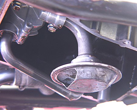
Touched up frame paint here and there. Reinstalled wiring and hoses. Dropped the oil pan to check for debris. Good thing to do when there is mileage on the engine and you are doing major work anyway.
|
|
Here's the oil pump and oil pump pickup screen. Found some sludge in here, not too much.
|
|
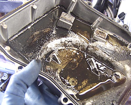
Here's the inside of the oil pan. Pretty grimy. Not too unusual however.
|
|
Installing the drive shaft. The splines at the engine end were greased first with moly grease.
|
|
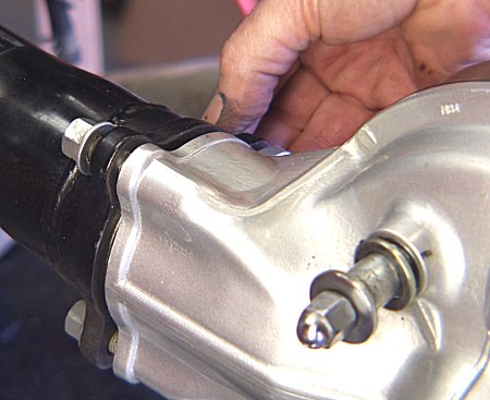
Tightening up the final drive unit, preliminary to doing the special tightening procedure later. This shot shows the newly painted finish on the totally rebuilt final drive to good effect.
|
|
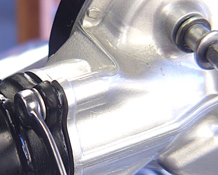
Another shot that shows the finish on the final drive case. Making progress.
|
|
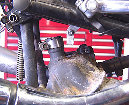
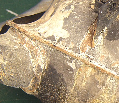
Today, Saturday November 22 (anniversary of Kennedy's death) was oil pan and muffler day. While we had the exhaust system dropped down to R&R the oil pan, went ahead and pulled it all the way off. Easy enough to R&R. Lot of corrosion there from your battery overflow incident, especially on the right side of course, same as the frame. I have been retouching up the paint in the frame and swingarm area, and will do the same with the exhaust. In the meantime, looking for a replacement exhaust or at least some mufflers, as yours are as you know dented and gouged, both sides.
|
|
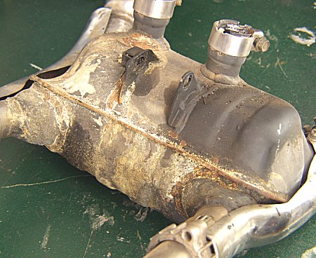
Close-up of the pre-chamber, the main muffler actually. Heavy corrosion, but I think an acid bath will fix it, followed by a goot repainting with some high-temp paint.
|
|
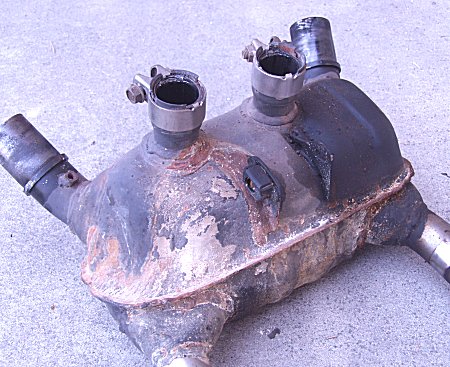
The same part with the muffs pulled off. On the pavement, forgot to reset the white balance on the camera so came out purple hued. Was important to see that the mufflers came off without too much trouble. They can be difficult at times.
|
|
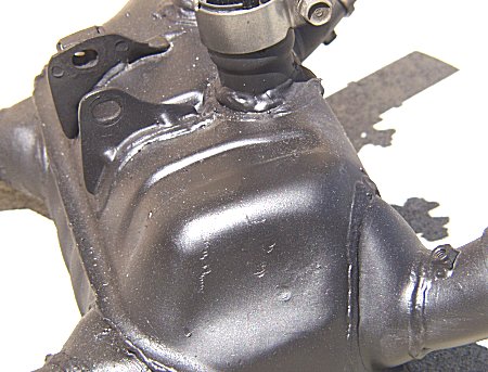
And the same part fully derusted and repainted with high temp paint and baked. Still have to touch up the clamps and polish up the head piples, but how we are in business again, exhaust-wise. Speaking of being in business again, I am back for good from training trips for the season, so am working on your bike now steady. I am committing to focusing on it even though I have taken in some carburetor work in the meantime.
|
|
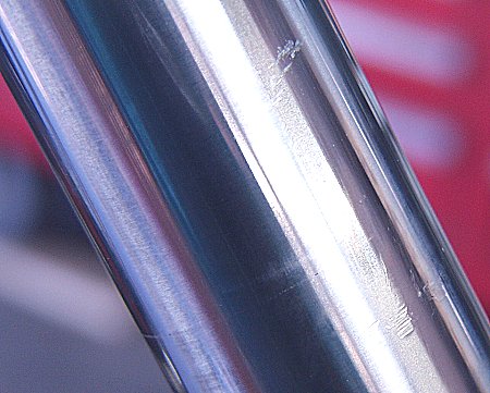
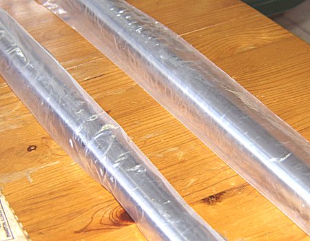
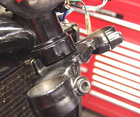
Today was going to be fork seals and steering bearings day. However, when I drained the fork oil, noticed very new oil, and then, upon removing the seals and fork lower sliders, this damage. Both tubes are scarred, this right side one more heavily than the left, but both are damaged and need to be replaced. Whoever was in there last to replace seals did not do the job professioally. I always use adhesive tape on the tube to protect it from the snap ring pliers, and I use a solid aluminum seal driver. I will be looking into the availability of the two tubes. Meantime, I will have to reassemble the front end to keep it secure on the lift and allow me to work on finishing up the wiring harness and electrical (regulator/recitifier in particular, whose holder is heavily corroded from battery acid damage and needs stripping and repainting. We're getting closer, Martin. Sorry about the delay.
|
|
Here are the tubes. I have checked them for dings, and for having the requisite internal shuttle valves (they do). Next they will be checked for straightness and for having the access holes in the right places.
|

|
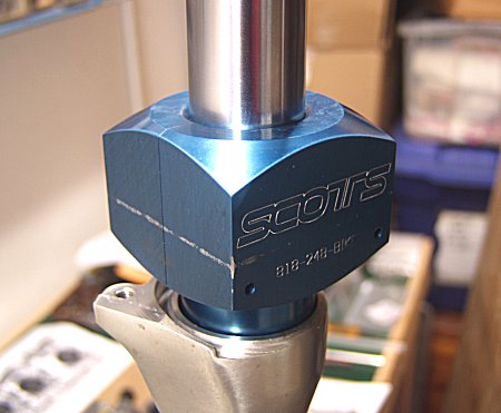
Checking the new tubes for straightness, and at the same time holding them off the workbench to facilitate inserting all the "guts," the valving and so forth.
|
|
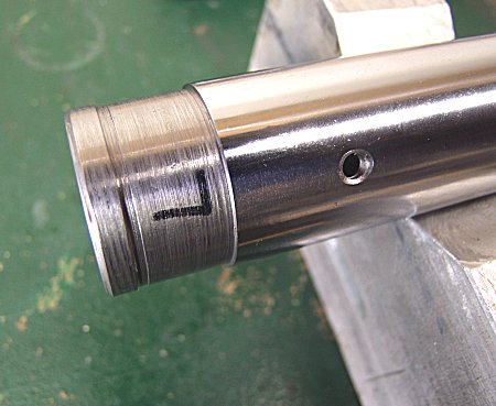
Closeup of the left side tube. Both tubes were marked, because on this bike the valving is not the same left to right.
|
|
Using the all-aluminum seal driver. Assembling the two fork legs.
|
|
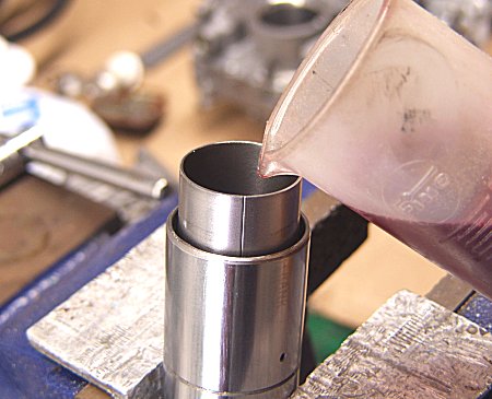
Pouring in the fork oil from a graduated beaker.
|
|
Forks done, starting on the steering bearings. Special factory Honda tool was used to remove the lower and upper races from the frame.
|
|
Races are installed in both frame and on the steering stem. New everything. Actually, the bearing assemblies in there were in remarkably good shape. Someone has been taking care of this bike, or maybe the steering bearings were replaced once before.
|
|
Front end back together, waiting only to do the spring scale measurement of bearing tension, which requires the wheel and brakes to be fitted. More soon!
|
|
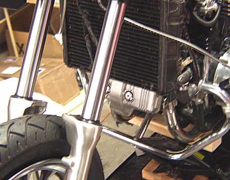
Well, back at it today. Taking shape, don't you think? Front end all assembled. Only the caliper chrome garnish to install. Even the radiator cover is on. Have an issue with the radiator cap. The custom cap is an automotive cap that is not original, and the chrome cover does not fit a stock cap. Will resolve it next go-around, Lord willing. New front tire.
|
|
Exhaust back on. But not mufflers yet. Eveything done except rear brakes, electrical, and...whatever I can't think of at the moment. :-) Preliminary inspection of the final drive indicates the oil showing my just be residual from the installation, but I'll make sure before I bless it.
|
|
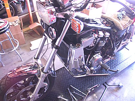
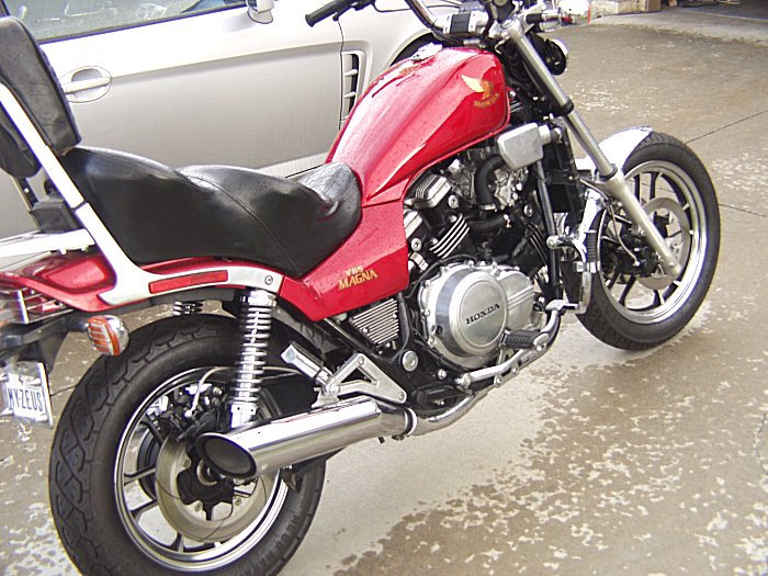
New turnsignals on, new handlebar. Bike is cleaning up nice. Still a bit of battery acid damage on the right muffler beauty cover. Bike is in overall very outstanding condition. A keeper for sure! More next time.
|
|
Finished up the electrical today. This is a picture of the battery box cover being repainted after removal of all the rust. What you see is bare metal being heated up where the rust was, to dry it out before repainting. Put the tank on, finished the clutch slave cylinder rebuild. Looking good. Have one problem though. Oil leak at clutch pushrod seal. This is going to be some work. Could tie us up beyond our target date in August.
|
|
The offending seal. Still determining what has to be done. Update soon.
|
|
Almost done! Touching up the frame tubes where the aftermarket radiator covers scratched up the paint.
|
|
Got the right angle drive off today, Saturday the 12th of Sept., after all the parts arrived.
|
|
I decided to do it by removing the clutch instead of disasembling the rear suspension. Gives us a chance to look around in there. Everything looks good.
|
|
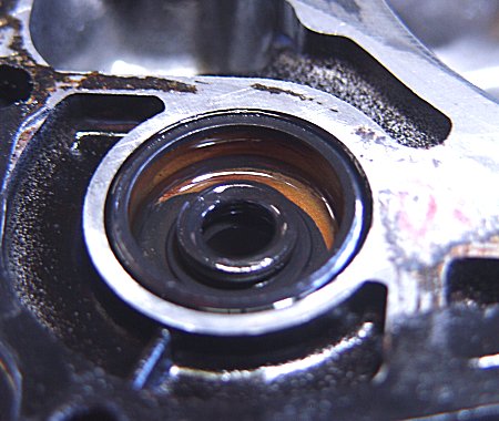
The errant seal. You see, it is removed from the back side of this cover that was removed from the engine. More updates later.
|
|
November 21st. New seal came in. Going back together. That's a piece of phone book paper at the bottom left, to check fit of cover to housing.
|
|
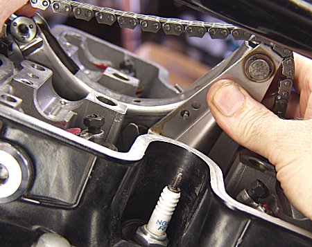
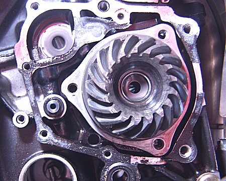
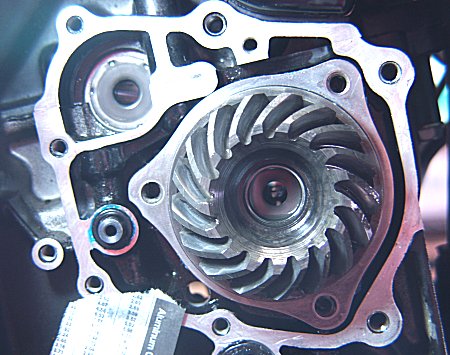
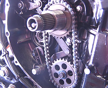
Thought you might like to see your oil pump drive. Just like the CBX, the Magna has its oil pump (and water pump on the opposite side) driven by the clutch. With the clutch removed, you can see the chain and sprockets. We put a new chain on when we were first in here. Forgive the poor pix. I forgot to set the white balance again. :-)
|
|
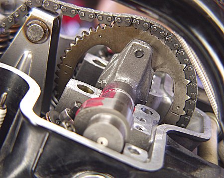
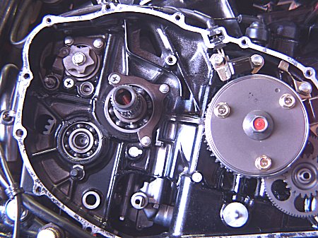
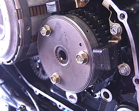
This is an interesting part. Thought you might like to see it. It is the starter drive clutch. This part allows the engine to spin up after starting, faster than the starter motor without stripping the starter motor out. It's a free-running clutch in other words. Technically known as a sprague clutch. What's even more remarkable is Honda gave this part double duty. It also contains the ignition triggers ("pulsers" in Honda-speak).
|
|
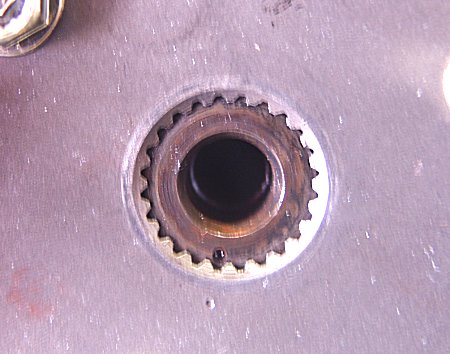
The part is splined, but has a set of timing dots. The Interceptor, a close cousin to the Magna, also has this part. Folks who raced the Interceptor back then used to remove this part and retime it one spline to advance the ignition timing.
|
|
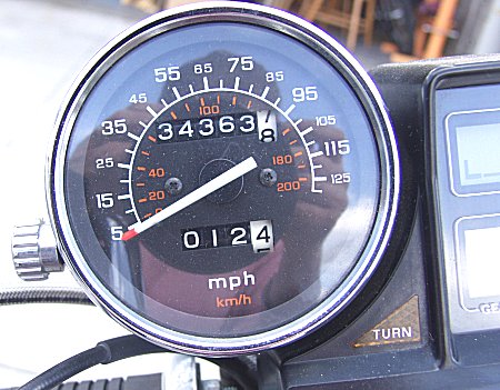
Yup. That's 12 1/2 miles I put on the machine this afternoon. Woohoo!
|
|
Still have a couple picayune things to sort out, and also I need to make sure the moisture showing on the bottom of the just-repaired oil leak is just melted grease and not still leaking on us. Stay tuned.
|
|
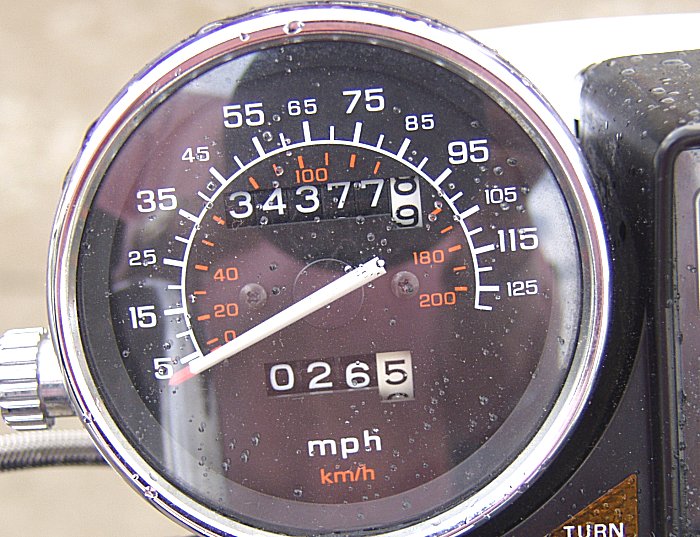
Put a few more miles on the bike after inspecting the right angle drive cover and adjusting the steering bearings. Bike runs good. Warms up quickly enough, even for a carbureted bike. I had forgotten just how seamless and electric like the power output is from these V4s. Very nice, and really the claim to fame of this series of bikes.
|
|
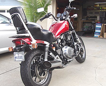
Looking good! I don't like the way the seat pushes against the sidecovers constantly. You're likely to lose those covers because of the seat. Just my feeling about it, not liking the seat much anyway. :-)
|
|
Wow! So that's what that lift looks like! I had fogotten! Hoping to see more of this very soon! :-)
|